Wiegand Keypad Garage Door — Thin-Edge ESPHome Reader
Contents
Overview
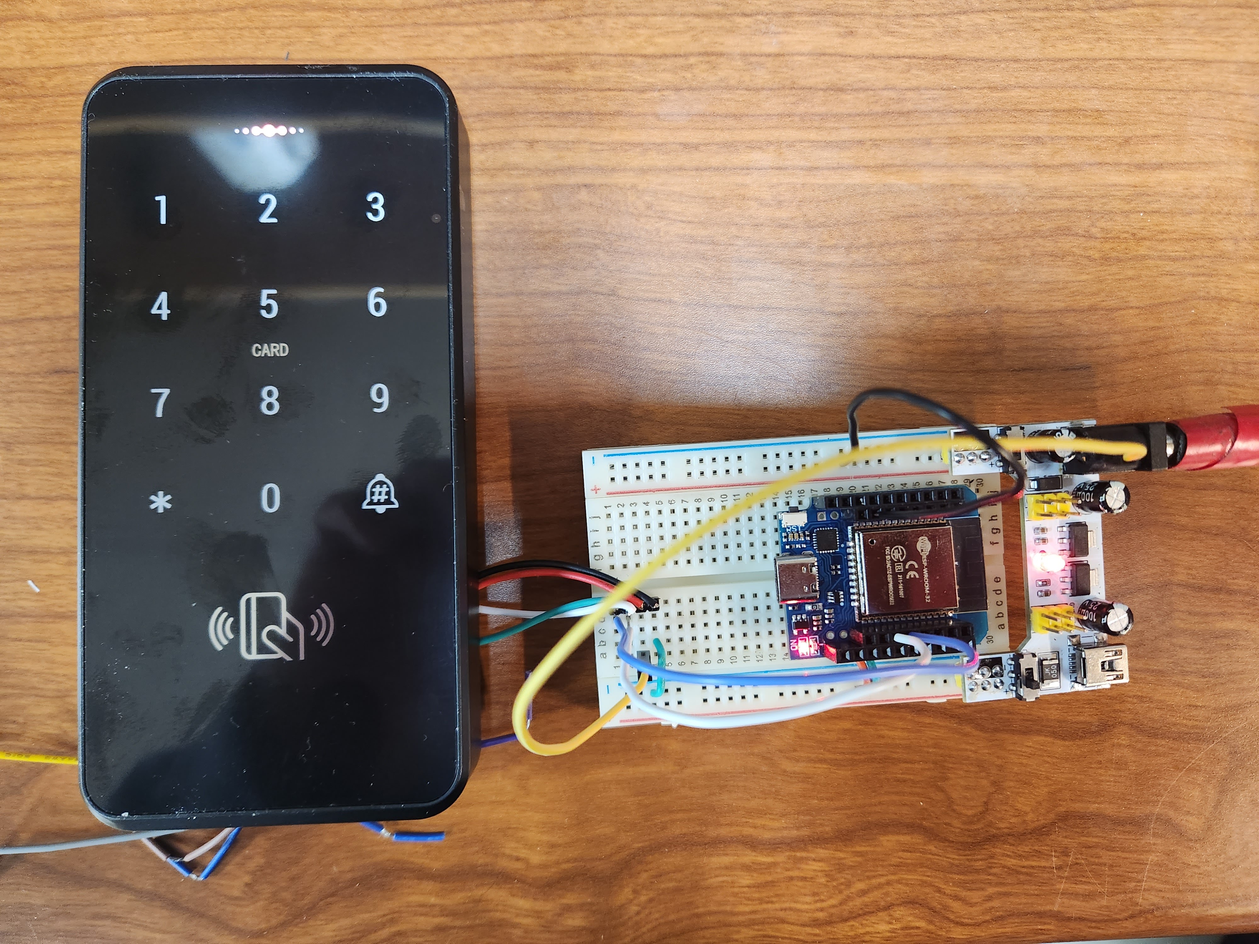
An ESPHome config for a Wiegand keypad reader for a garage door. The design is built around a thin-edge philosophy — the device’s only job is to capture input and relay it upstream to Home Assistant, with no local secret storage or access-control logic on the device itself.
The reader originally ran on its own dedicated ESP32 mounted in the keypad enclosure. It’s since been folded into the ESP32 already running the garage’s RATGDO board — see Hardware Evolution below for why and how.
Wiegand Device Compatibility
This config works with any Wiegand-compatible reader — keypads, RFID readers, or combo units. However, many low-cost devices ship in a host mode where they store PINs internally and control a relay output directly. These devices need to be reconfigured to Wiegand output mode before they’ll work here. The reconfiguration process varies by device but typically involves a programming card sequence or a DIP switch. Once in Wiegand mode the device stops managing access locally and simply outputs credentials on the D0/D1 data lines — exactly what this config expects.
How It Works
The wiegand component reads raw input from a Wiegand-protocol keypad (or RFID reader) connected on two GPIO pins (D0/D1), handling raw key presses, tag reads, and raw bit streams. On top of that, the key_collector component assembles individual key presses into a complete 4-digit PIN:
#— enter / submit*#— clear / reset- 4-second inactivity timeout
When a complete PIN is entered (or a tag is scanned), the value is published to a text_sensor called Keypad Code, which exposes it to Home Assistant. After a 500ms delay to ensure HA picks up the value, the sensor is cleared back to "0" to prevent duplicate processing.
That’s the full extent of what the device does — collect the credential and send it.
Design Intent
All actual logic — PIN validation, authorization decisions, door actuation — lives in Home Assistant automations, not on the ESP32. This approach:
- Avoids storing PINs or secrets in ESPHome firmware (where they’d sit in plaintext flash memory)
- Centralizes access control where it can be audited and changed without reflashing hardware
- Keeps the edge device simple and easily replaceable
On the original standalone reader, the ESP32 CPU was clocked down to 160 MHz (from the default 240 MHz) to reduce power consumption, since the workload was minimal. Now that the reader shares an ESP32 with the RATGDO firmware, that workload assumption no longer holds — see below.
Hardware Evolution: From a Standalone Reader to a RATGDO Integration
The original build ran the Wiegand reader on its own ESP32, mounted inside the keypad’s outdoor enclosure alongside the RFID module and a 5V-to-12V boost converter that powered them. D0/D1 were wired straight to the ESP32’s GPIOs with no level shifting at all — since the keypad idles those lines at 5V against 3.3V-only-tolerant pins, the chip’s internal ESD clamp diodes were conducting continuously just to survive the idle state, a steady voltage stress on the pins. That ESP32 eventually failed and needed replacing; prolonged outdoor temperature extremes may have played a part too, though the enclosure was weatherproof and shielded, so that cause isn’t fully confirmed — the direct 5V-to-3.3V wiring is the more concrete suspect.
The replacement coincided with a second, larger change: the garage door itself moved from a Meross MSG100 smart door controller/monitor to a RATGDO board running the community ratgdo ESPHome component. Since the RATGDO already runs its own ESP32 inside the garage, that migration was the natural point to fold the keypad reader into it rather than replacing the failed standalone ESP32 in place.
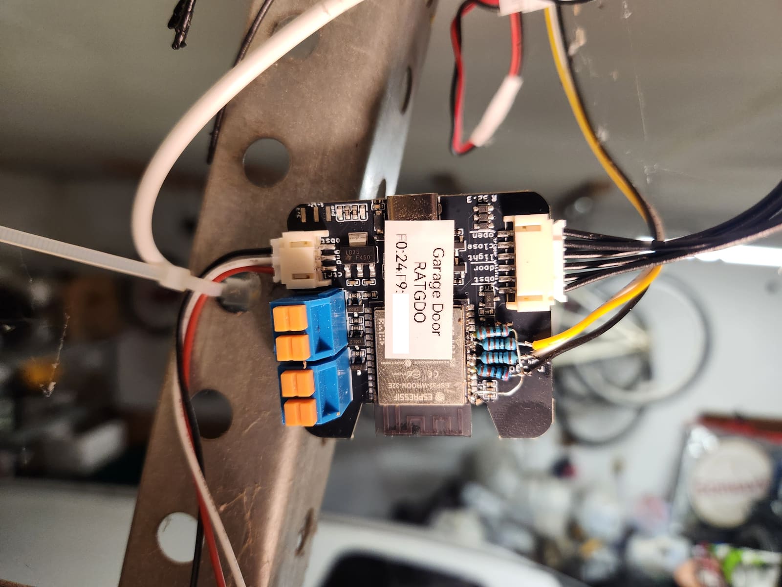
The Wiegand D0/D1 lines (idling at 5V) go into the RATGDO’s 3.3V-logic ESP32 through resistor voltage dividers — the small resistor cluster visible on the board above. The 5V-to-12V boost converter that powers the keypad’s RFID reader and backlight also moved out of the keypad enclosure, onto an inline pigtail near the RATGDO. That leaves the keypad end of the run with no active electronics at all — just a simple 4-wire cable (Wiegand D+/D-, 5V, and 12V) back to the pigtail.
This consolidation also fixed a problem the original layout had been quietly living with: with the ESP32 and the boost converter both crammed into the keypad enclosure right next to the RFID reader, the ESP32’s Wi-Fi saw occasional packet loss — most likely RF interference from one of its close neighbors. Moving the active electronics out to the RATGDO removed both the interference source and the weather exposure in one move.
In hindsight: resistor dividers work, but a single series diode per line (cathode toward the keypad, anode toward the GPIO) is simpler and doesn’t load the open-collector line. See One Diode to Read a 5V Wiegand Keypad on a 3.3V ESP32 for the technique — some RATGDO GPIO inputs may already carry their own clamping-diode protection, which would make even that external diode unnecessary.
Current Firmware
The RATGDO now runs both the door controller and the keypad reader from one ESPHome config, composed from packages:
substitutions:
  esphome_name: garage-door
  friendly_name: Garage Door

packages:
  network: !include .network.yaml
  web_server: !include .web-server.yaml
  wiegand_keypad: !include .wiegand-keypad.yaml

esphome:
  name: ${esphome_name}
  friendly_name: ${friendly_name}
esp32:
  board: esp32dev
  framework:
    type: esp-idf

external_components:
  - source: github://ratgdo/esphome-ratgdo@main
    components: [ratgdo]
    refresh: 1d

safe_mode:

logger:
  level: INFO

preferences:
  flash_write_interval: 1min

ratgdo:
  id: my_garage_door_opener
  input_gdo_pin: GPIO21   # RX from opener data bus
  output_gdo_pin: GPIO17  # TX to opener data bus
  input_obst_pin: GPIO4   # obstruction sensor (safety beam)
  protocol: secplusv1     # LiftMaster 41AC050-2, purple learn button = Security+ 1.0
The rest of the config exposes the door itself to Home Assistant: a cover for the door, light and lock (remotes) entities, binary_sensors for obstruction/motion/button plus a physically-wired reed switch for door-closed state, numbers for the rolling code counter and open/close durations, and template buttons for sync and manual toggle.
The wiegand_keypad Package
This is the reader logic described above, now just one package among several instead of the whole device. D0/D1 land on GPIO33/GPIO35 — through the resistor dividers pictured above — and feed the wiegand: and key_collector: components that were previously the entire standalone config:
substitutions:
  wiegand_d0: GPIO33
  wiegand_d1: GPIO35

wiegand:
  - id: mykeypad
    d0: ${wiegand_d0}
    d1: ${wiegand_d1}
    on_key:
      - lambda: ESP_LOGI("KEY", "received key %d", x);
    on_tag:
      - lambda: ESP_LOGI("TAG", "received tag %s", x.c_str());
      - text_sensor.template.publish:
          id: keypad
          state: !lambda "return x.c_str();"
    on_raw:
      - lambda: ESP_LOGI("RAW", "received raw %d bits, value %llx", bits, value);

key_collector:
  - id: pincode_reader
    source_id: mykeypad
    min_length: 4
    max_length: 4
    end_keys: "#"
    clear_keys: "*#"
    allowed_keys: "0123456789"
    timeout: 4s
    on_progress:
      - logger.log:
          format: "input progress: '%s', started by '%c'"
          args: ['x.c_str()', "(start == 0 ? '~' : start)"]
    on_result:
      - logger.log:
          format: "input result: '%s', started by '%c', ended by '%c'"
          args: ['x.c_str()', "(start == 0 ? '~' : start)", "(end == 0 ? '~' : end)"]
      - text_sensor.template.publish:
          id: keypad
          state: !lambda "return x.c_str();"
      - delay: 500ms
      - text_sensor.template.publish:
          id: keypad
          state: "0"
    on_timeout:
      - logger.log:
          format: "input timeout: '%s', started by '%c'"
          args: ['x.c_str()', "(start == 0 ? '~' : start)"]

text_sensor:
  - platform: template
    name: "Keypad Code"
    id: keypad
Tag reads publish straight to the Keypad Code text sensor via on_tag; PIN entry goes through key_collector, which only publishes on_result — a completed 4-digit code terminated by #, or a reset on *#/timeout. Either path lands on the same sensor, so Home Assistant only ever has one place to watch. The on_key/on_raw handlers just log at INFO for visibility — no logic runs on the device itself, matching the thin-edge design described above.
Configuration Practices
Network config is pulled from an external .network.yaml include, keeping WiFi credentials separated from the main config — a clean practice for version control. Production logging is set to INFO, with DEBUG-level messages available on the key-press and raw-data handlers for troubleshooting.